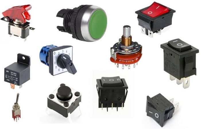
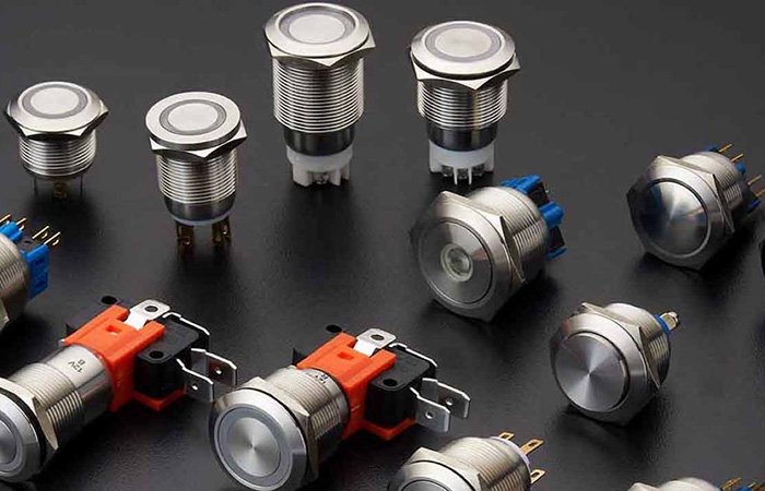
Push buttons are widely utilized across various industries. Whether in residential or commercial settings, actuators for switching power circuits on and off are commonly found.
In industrial environments, routine shift changes require operators to understand switch symbols.
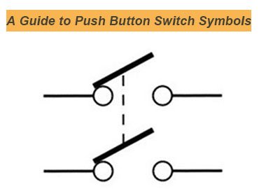
These switch symbols ensure a universal schematic representation and indicate the current state of the circuit and switch to prevent accidents. Today, we will explore various types of push button symbols and understand how they can assist you.
What is a Push Button Switch?
A A push button switch is an electromechanical switch that requires manual operation to turn on/off. Mechanical actuation controls the circuit.
There are two main categories: A latching switch maintains the circuit in its new position until pressed again, while a momentary switch returns to its default position when released.
Different push button switches have varying positions and circuit opening/closing patterns.
The Importance of Push Button Switch Symbols
Understanding push button switch symbols is essential, as they are highly useful.
Clear Identification
Switch symbols clearly indicate circuit types. For example, an NC switch is depicted differently from an NO switch. Similarly, it is easier to distinguish between latching and momentary switches.
Prevent Wiring Issues
Accurate symbols prevent incorrect wiring connections and avoid equipment damage, ensuring system safety.
Improve Efficiency
There is no need to spend hours identifying faults. Symbols can clearly indicate issues and help resolve them faster, improving efficiency and providing comprehensive support.
Ensure Compliance
Many international and local authorities require symbolic representation. Standards such as IEC 60617 and ANSI/IEEE define how symbols should be designed. This universality and compliance facilitate smooth technical collaboration among engineers.
Simplify System Design
Operators and engineers do not need to read lengthy descriptions about circuits and switches. A straightforward symbolic representation clearly conveys circuit position, control logic, and electrical behavior, simplifying design and enhancing understanding.
Push Button Switch Symbols: Comprehensive List
| Push Button Switch | Meaning | Function | Image |
| Normally Open (NO) | Two straight lines with a noticeable gap between them. | Pressing the button closes the circuit. | 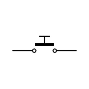 |
| Normally Closed (NC) | Two lines connected, with no gap between them. | Pressing the button opens the circuit. | 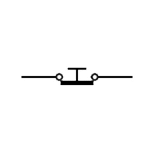 |
| Momentary Switch | Similar to NC/NO symbols but specific to momentary switches. | Remains active while the button is pressed. Releasing returns the circuit to its previous state. | 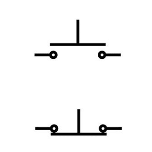 |
| Double-Pole Single-Throw (DPST) | Two parallel lines, each with a gap or connection. | Allows control of two circuits simultaneously. | 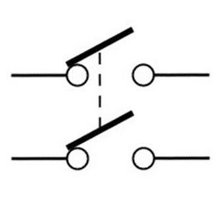 |
| Double-Pole Double-Throw (DPDT) | Two rows with different paths. | Switches two circuits between different paths on/off. | 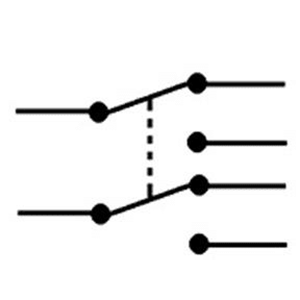 |
| Pushbutton with Delayed Action | Two lines with a gap and a time delay indicator. | Activates or deactivates after a set specific time. | 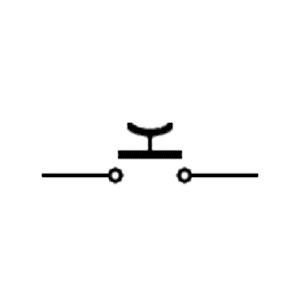 |
| Mushroom Head Pushbutton | An emergency stop button with a large rounded head. | Press to halt operations during emergencies. | 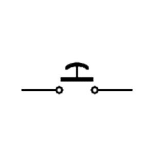 |
| Maintained Contact One Double Circuit | This switch engages two circuits. | Keeps both circuits closed after pressing for continuous operation. | 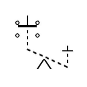 |
| Maintained Contact Two Single Circuits | A button that contacts two circuits. | Keeps each circuit engaged independently after pressing. | 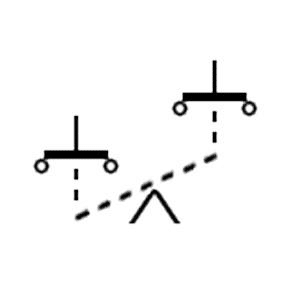 |
| Fast Closing Pushbutton | Features arrows or lines indicating rapid closure. | Provides quick activation where immediate connection is required. | 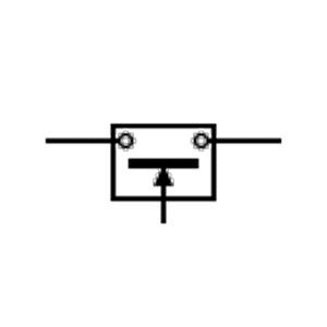 |
| Fast Opening Pushbutton | Symbol with arrows or lines indicating rapid disconnection. | Enables swift disconnection, used in systems requiring fast disengagement or emergency stopping. | 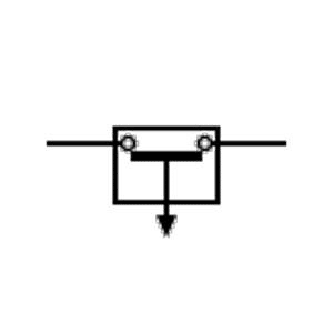 |
| Pull Cord Pushbutton | Icon combining a pull cord and push button, indicating activation by pulling. | Pulling the cord is safer than pressing a button. | 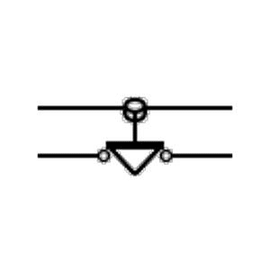 |
| Padlock Pushbutton | A padlock icon near the button. | Designed to be locked in position, preventing unauthorized use or accidental activation. | 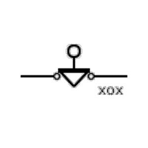 |
| Three-Position Selector Switch | A switch with three stable positions | Allows selection between three modes, e.g., Forward/Off/Reverse or Auto/Manual/Off |  |
| Spring Return Selector Switch | Returns automatically to default when released | Momentary control, jog actions, temporary overrides | 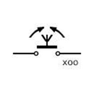 |
| Joystick Switch | Lever that moves in multiple directions, controlling contacts | Directional control for machinery, cranes, hoists, or automated systems | 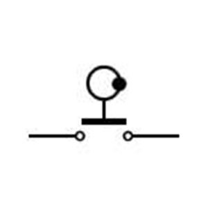 |
| Telegraph Key Switch | Pivoting lever for momentary contact | Sends signals (e.g., Morse code), training simulators, and momentary activation | 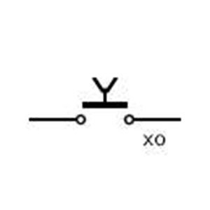 |
| Circuit Switch Pushbutton | Standard pushbutton controlling a circuit | Directly opens or closes a circuit manually on panels or machinery | 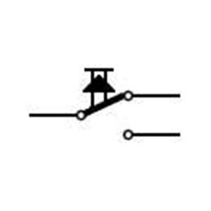 |
Common Mistakes in Push-Button Switch Symbols
There are a few common mistakes in push-button symbols that can cause issues. These include:
NO and NC symbols
Mixing up the NO and NC symbols is a problem. Symbols should depict their default state when not pressed. Slight mistakes can cause mishaps.
Unapproved Symbols
Symbols approved by IEC and IEEE should be used. If you are using unapproved symbols, it will trouble the engineers to understand the symbols properly.
Not Showing Illuminated Circuits
Illuminated circuits require an LED or lamp symbol in addition to normal switch symbols. If you fail to provide it, it will lead to errors during operations.
Forget labelling E-Stop Buttons
E-stop buttons are crucial and need emergency handling. They should have a proper symbol that is universally recognized.
Inaccurate Terminal Numbering
A misnumbered diagram causes the operation failure. You should properly number each terminal and ensure a safe trip.
FAQs
1. Do illuminated push buttons have unique symbols?
Yes, illuminated push-button switches have a distinctive symbol. For example, they have an additional lamp symbol in the switch to show off their illuminated symbol.
2. How are emergency stop (E-Stop) buttons represented in schematics?
E-stop buttons have a distinct symbol, such as a mushroom-shaped actuator, an NC (Normally Closed) contact symbol, and an optional latching indicator. It shows pressing them can turn off the supply in the circuit.
3. Are push-button switch symbols the same across all countries?
No. It depends on the IEC and IEEE usage in the countries. For example, most countries use IEC 60617 and have the universal symbols across their regions. North American regions use the ANSI/IEEE-based symbols and have the same throughout their regions.
4. What standards define push-button symbols?
There are three most common technical standards for push button symbols. For example:
- IEC 60617—international standard for graphical symbols used in diagrams
- ISO 7000—graphical symbols for public information
- ANSI Y32 / IEEE 315—U.S. standard for electrical and electronics diagrams
Conclusion
Understanding push button switch symbols is necessary in many ways, as it can highlight the switch position. Moreover, you can recognize the switch type and function. The universality of switch buttons across countries allows a better understanding of the operators and helps the system operate more efficiently with predefined systems.